

Press Announcement
September 25, 2026
Cooling at Hall Scale Is a Chemistry Problem: Inside the DCX 8 MW FDU
September 25, 2026
Cooling at Hall Scale Is a Chemistry Problem: Inside the DCX 8 MW FDU
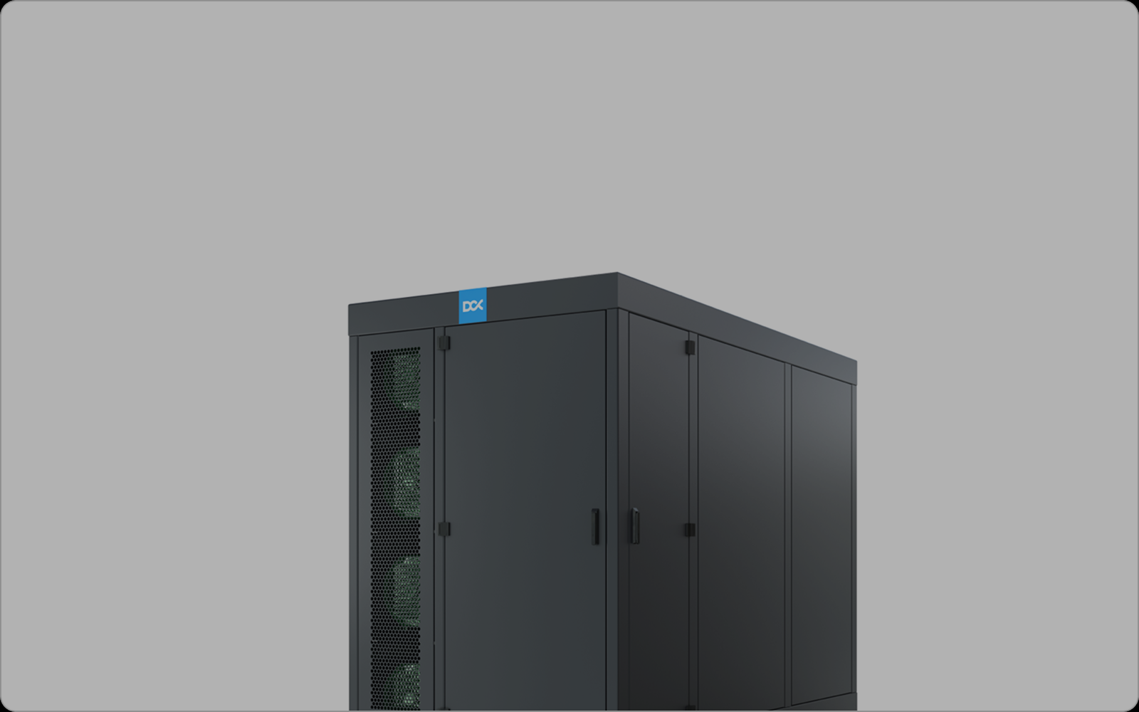
Up to 8.15 MW per unit, a coolant distribution unit stops being a rack accessory and becomes hall infrastructure. One DCX Facility Distribution Unit (FDU) carries roughly the load of six 1.3 MW row CDUs, through centralized technology cooling system (TCS) supply and return loops.
When one unit cools a hall, the coolant is the system
Up to 8.15 MW per unit, a coolant distribution unit stops being a rack accessory and becomes hall infrastructure. One DCX Facility Distribution Unit (FDU) carries roughly the load of six 1.3 MW row CDUs, through centralized technology cooling system (TCS) supply and return loops.
That concentration is the point of the design: fewer pumps, fewer heat exchangers, one control system. It also means the condition of one volume of coolant now decides the thermal health of every cold plate in the hall.
Capacity gets an FDU specified. Control of the cooling medium decides whether it still delivers its rated approach temperature in year five. That is why DCX builds coolant monitoring and chemical dosing into the FDU skid, rather than leaving them to a separate contract.
What the FDU is: a CDU sized for the hall, not the row
The FDU is a coolant distribution unit moved upstream. It sits outside the white space and serves a whole data hall through centralized supply and return loops, instead of dozens of in-row units each with its own pumps and heat exchanger (Data Center Frontier).
Like any CDU, it is the boundary between two loops. On one side is the facility water system (FWS), fed by dry coolers, cooling towers or chillers. On the other is the technology cooling system (TCS), the closed loop that reaches the cold plates. A liquid-to-liquid heat exchanger moves heat across without mixing the two fluids.
Sources: DCX launch release, January 2026; loop reach from Data Center Frontier.
The 2 K approach is the number that matters most for warm-water operation. It means the TCS can be supplied at 45 °C from facility water at roughly 43 °C, which widens the hours in which dry coolers alone can reject the heat. It is also the number most exposed to what happens to the fluids over time.
How a TCS loop loses performance: it drifts, it doesn't break
Coolant rarely fails in one event. It drifts, and every drift path ends in the same two places: more thermal resistance at a cold plate or heat exchanger, or metal leaving the loop.
- Inhibitor depletion. Corrosion inhibitors are consumed as they protect the loop. As they deplete and dissolved solids accumulate, the fluid turns corrosive (Dell). OCP makes copper inhibitor mandatory for PG-based TCS fluids.
- Glycol drifts. Topping up with water dilutes PG25. Below about 25 vol% propylene glycol the fluid stops being biostatic; above the range, viscosity and pump energy climb.
- Degradation acids. Glycol slowly breaks down into acids that consume reserve alkalinity, the fluid's buffering capacity, and then pull pH down.
- Particulates. Corrosion products and installation debris lodge in cold-plate microchannels. OCP recommends side-stream filtration below 5 µm on 10% of loop flow, plus coarser inline filters of around 50 µm to protect heat exchangers and quick connects.
- Mixed metals. Brass fittings can shed zinc, and worn plating on quick connects creates galvanic couples. OCP recommends annual zinc analysis wherever brass is wetted.
- Fouling on the facility side. In the FWS, calcium, magnesium and silica scale and biofilm coat heat-exchanger surfaces, adding thermal resistance and pump head (Dell). On a 2 K-approach unit, that film shows up directly as a higher approach.
The OCP guideline for PG-based TCS fluids defines what "in spec" means (OCP):
Warm-water operation tightens these margins. OCP notes that closed TCS loops typically run below 49 °C and calls for a wetted-materials review above 66 °C. With 45 °C supply and a 10-15 K rise across the racks, return coolant sits at 55-60 °C, and every degradation path above runs faster there.
Why quarterly sampling does not scale to a hall
The industry's own guidance draws the line. For TCS loops above 250 gallons (about 950 L), or for critical systems, the OCP guideline recommends continuous monitoring of fluid chemistry, pH, corrosion rate and turbidity (OCP). A hall loop with more than 50 m of large-bore headers holds many times that volume.
Detection lag. The default regime is an on-site check each quarter and a laboratory analysis once a year. That leaves up to three months in which an excursion, such as a contaminated rack refresh or a top-up with poor water, runs unseen.
Blast radius. In a row architecture, a bad fluid event stays inside one CDU's loop. Where an FDU feeds racks directly, it reaches every rack on the hall loop. Centralizing trades many small risks for one larger one, and that trade only pays off if the one loop is watched continuously.
Refresh cycles. The FDU is designed to outlast several generations of IT hardware. OCP's guidance is written for exactly that case: cooling infrastructure reused through multiple hardware refreshes. Each refresh brings new wetted parts, residues and fluid into the loop, and continuous monitoring turns it into a measured event with a before-and-after trend.
Correction without downtime. OCP also asks for chemical-injection ports so chemistry can be corrected while the loop keeps running. Onboard dosing is that recommendation, built into the unit and automated.
What sits in the skid: sense, correct, hold, report
DCX ships the 8 MW FDU with inline water-quality sensors and a water treatment system as standard equipment (launch release). They sit alongside four pumps in N+1 and diagnostics designed for predictive maintenance (Data Center Frontier). Functionally, the coolant-control package does four jobs.
- Sense. Inline sensors read the coolant continuously instead of once a quarter. On DCX's FDU HMI, featured functions include system overview, water quality monitoring, system status, and chemical dosing & treatment.
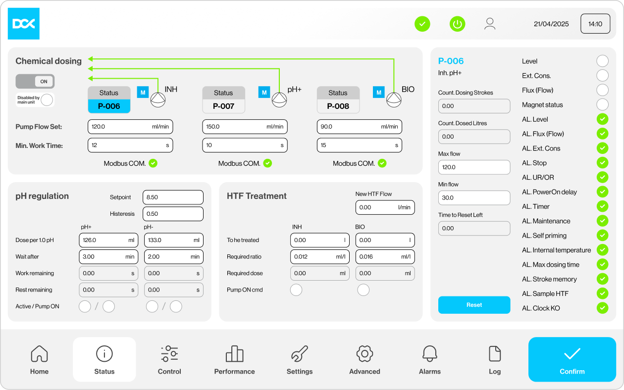
- Correct. Onboard dosing restores inhibitor level and pH while the loop keeps running. This is OCP's chemical-injection recommendation, automated and closed around the sensor readings. The FDU uses three dosing channels for inhibitor, pH regulation and biocide treatment, with configurable dosing flow, minimum run time and pH-control parameters.
- Hold. The FDU family adds automatic coolant levelling, leak detection and condensation-free control that keeps supply above the dew point. Automatic levelling removes the ad hoc top-up, the usual route to diluted glycol.
- Report. Chemistry trends sit next to flow, pressure and temperature on one controller.
In-skid treatment also changes which cooling medium is practical. DCX describes the FDU's treatment station as keeping the cooling medium pure without the performance penalty of PG25. The physics is simple: PG25 carries about 3.9 kJ/kg·K against water's 4.18, at more than twice the viscosity (Dell). That trade-off can still be worthwhile in applications where freeze protection, corrosion protection and operational resilience are more important than maximum heat-transfer efficiency.
Water's advantage is only usable with active chemistry control. Without glycol's biostatic effect, it needs filtration, pH control and biocide dosing to stay clean. Treatment in the skid makes treated water a real option wherever the IT vendor's warranty allows it, some server OEMs still require PG25 on the TCS. For example, Dell specifies PG25 as the only authorized liquid coolant for certain direct-liquid-cooled PowerEdge platforms (Dell).
Live monitoring and control from the FDU's own HMI
Everything above is visible and adjustable on the FDU's touchscreen. An operator gets from a one-line verdict to an individual dosing pump in two taps.
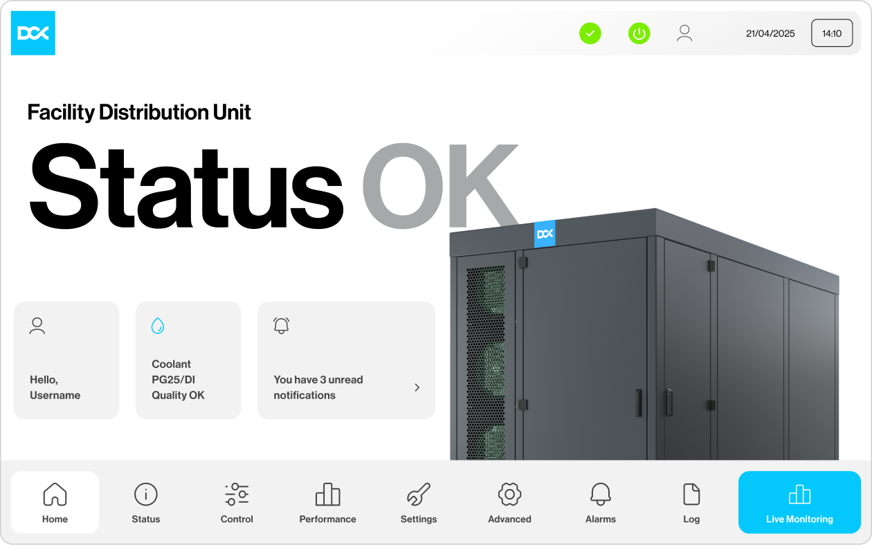
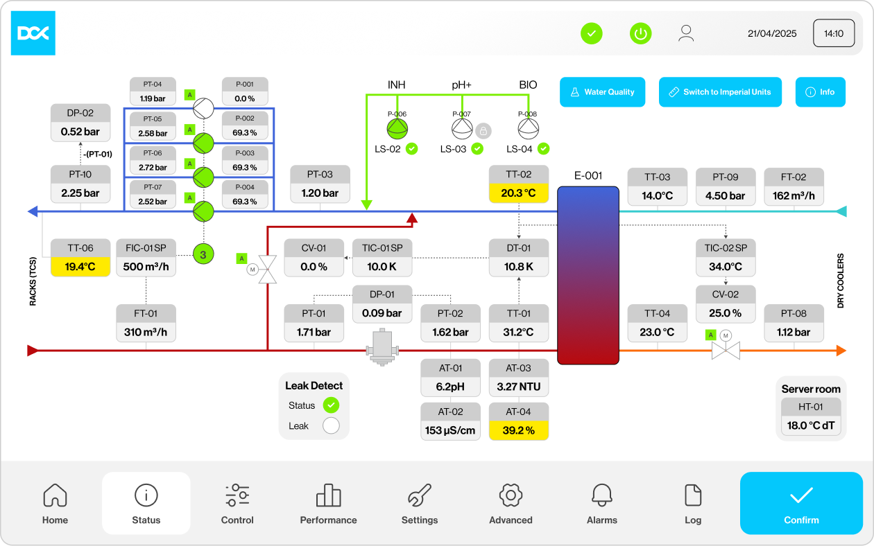
The whole loop on one screen. The home screen reduces the unit to one verdict, "Status OK", with a separate coolant-quality flag for PG25 or deionized-water operation (Figure 1). The live P&ID shows both sides of heat exchanger E-001: the TCS to the racks and facility water from the dry coolers (Figure 2). Supply and return temperatures, the TCS ΔT setpoint and bypass valve, the flow setpoint, three duty pumps and the standby pump, filter differential pressure, leak detection, the inline analysers and the three dosing injection points all sit on the same drawing.
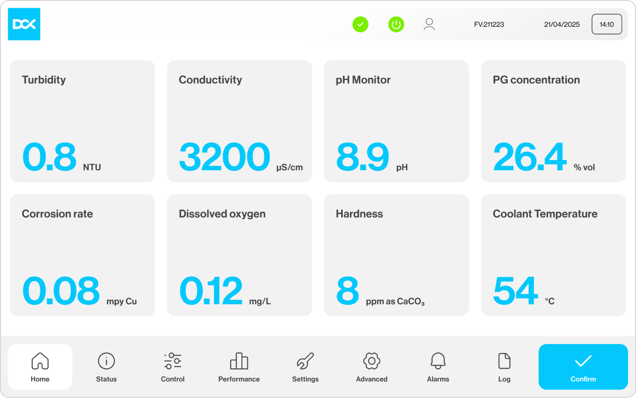
Eight coolant parameters, live. The water-quality view reads turbidity, conductivity, pH, PG concentration, copper corrosion rate, dissolved oxygen, hardness and coolant temperature continuously (Figure 3). That covers every parameter OCP asks large loops to monitor continuously: chemistry, pH, corrosion rate and turbidity. In the example, pH 8.9, 26.4 vol% glycol and 8 ppm hardness sit inside OCP's PG25 ranges, and the 0.08 mpy copper corrosion rate is well under the 0.22 mpy limit OCP uses to qualify fluids.
Closed-loop dosing, including make-up. Three Modbus-connected dosing pumps handle inhibitor with pH raise, pH reduction and biocide, each with its own flow setting, minimum run time, tank-level monitoring and alarm set (Figure 4). pH is held at a setpoint (8.50 with 0.50 hysteresis in the example) using a calibrated dose per pH unit and a wait after each dose, so the loop mixes before the next correction. When fresh fluid enters the loop, inhibitor and biocide are dosed in proportion to the added volume, and every stroke and dosed litre is counted, which produces the dosing record OCP asks operators to keep.
Why coolant control is the FDU's decisive advantage over ten years, not ten days
Capacity and approach temperature are measured on commissioning day. Coolant control decides whether those numbers still hold after years of warm-water operation and several IT refreshes. That makes it the feature with the longest payback in the unit.
Approach stability is where the money is. A 2 K approach is what lets 45 °C coolant come from roughly 43 °C facility water, and so what lets dry coolers carry the load for more of the year. Every tenth of a kelvin lost to fouling has to be bought back with colder facility water. An FDU that logs approach against load also makes FWS-side fouling visible early, even though FWS treatment usually stays with the building owner.
One owner for the loop. When hydraulics and chemistry control live in one unit under one controller, there is no interface to argue over when a parameter drifts. Chemistry delivered as a separate service around a CDU can work, but it adds a contract boundary exactly where fast decisions matter.
The records write themselves. OCP asks operators to keep a file per system with every fluid analysis and every inhibitor addition, including date, amount and type. Continuous sensing and logged dosing produce that file automatically, which is also the evidence IT vendors look for when a cold-plate warranty is questioned.
Fluid life is earned. OCP puts achievable PG fluid life at about five years, if the loop stays within its guidelines. Replacing the fluid in a hall-scale loop means draining, flushing twice and refilling, with the loop out of service. Staying in spec is what defers that event.
Nine questions to ask any CDU supplier about coolant control
These questions separate a unit with coolant control built in from one with a sampling port and a service contract.
1. Which parameters are measured inline, and how often? OCP's list for large loops is chemistry, pH, corrosion rate and turbidity.
2. Is correction automatic? Which chemicals, how many dosing channels, and what setpoints and limits?
3. What filtration is on the unit? OCP calls for side-stream filtration below 5 µm on 10% of flow; at 550 m³/h that is about 55 m³/h.
4. Is the coolant-control package factory-integrated and tested with the unit, or assembled on site?
5. How are readings and dosing events logged, exported to the BMS or DCIM, and retained as warranty evidence?
6. What happens during an IT refresh: baseline capture, alarms, isolation of the affected branch?
7. Which cooling media does the unit support, and which IT vendors have approved them?
8. Does the controller trend approach temperature against load, so heat-exchanger fouling shows up early?
9. When a parameter drifts, who is accountable: the CDU maker, the fluid supplier or a service contractor?
The next race is not megawatts
The last two years of CDU launches were a race to more megawatts per unit. As hall-scale units become normal, the difference between them will be how long each one holds its rated approach, flow and cleanliness.
DCX's answer is to treat the cooling medium as part of the machine. In the FDU it is measured, corrected and recorded inside the same skid that moves it.
Sources
- DCX Liquid Cooling Systems announces new 8MW coolant distribution unit, Business Wire, 23 January 2026
- DCX launches comprehensive ECDU portfolio, Business Wire, 11 March 2026
- From row-level CDUs to facility-scale cooling, Data Center Frontier, 5 February 2026
- Guidelines for using propylene glycol-based heat transfer fluids in single-phase cold plate-based liquid cooled racks, Open Compute Project, 2022
- Liquid coolants guidance for TCS and FWS, Dell Technologies whitepaper
About DCX Liquid Cooling Systems
DCX Liquid Cooling Systems is a premier global manufacturer offering an extensive range of sustainable liquid cooling solutions, including both Direct Liquid Cooling and Immersion Cooling technologies. The company designs & manufactures Server Immersion Enclosures, Coolant Distribution Units (CDUs) including Hyperscale FDU (Facility sized CDU) system, CPU and GPU coldplates, manifolds and other components of liquid cooling system. DCX delivers Hydro & Immersion Containers and facility-based systems. DCX supplies Immersion Optimised Dry Coolers and a Thermasafe Dielectric Engineered Fluids. Hardware solutions are complemented with liquid cooled data hall design and implementation services, making DCX the first choice for liquid cooling systems’ supplier.
For More Information,
Please Contact
Jacek Dolny
Marketing Manager
jacek.dolny@dcx.eu

We Will Guide You the Whole Time
Everything starts with conversation. Trust us with your project and get us to work on your idea
Invite Us to Your Project
We support both small entities and large enterprises. Initial system design – free of charge.

Let’s Chat with Us
If you have a liquid cooling or heat reuse project – we are yours to talk. Free of charge.

Get the Support
A comprehensive remote, and on-site service. Included with every system we deliver.

Liquid Cooling Explained
Discover the future of data center cooling through a series of short, expert-led videos. Our CTO, Maciek Szadkowski, answers the most important questions, debunks common myths, and reveals what really matters when it comes to modern liquid cooling systems.
Watch the Series
Tell Us About Your Project
The more you tell us up front, the faster we can come back with a real design rather than a brochure. Where possible, include:
- IT load: target capacity in MW, and rack density in kW
- Hardware: GPU or accelerator platform, rack format (19", 21", ORV3), cold plate or immersion
- Loop conditions: available facility water temperature and flow, or "not decided yet"
- Heat rejection: dry coolers, chilled water, district heating, or open
- Site: city and country, plus design ambient temperature
- Timeline: target energisation date and whether this is new build or retrofit
Contact