
Blog
October 28, 2026
Clean loop, reliable cooling: Why coolant cleanliness matters in AI data centers?
Warsaw, Poland, October 28, 2026
Why Coolant Health
is Becoming an Uptime Issue for AI Data Centers?
Most data center cooling systems are at their cleanest at handoff. The drawings are current. The acceptance tests are fresh. The equipment is ready. But it has not yet experienced months of maintenance, changing workloads, and system expansions. Then normal operations begin. A liquid cooling loop has a life beyond commissioning. Discover why coolant health is becoming an uptime issue for AI data centers.
Coolant Health
Clean coolant is essential for reliable AI infrastructure.

Continuous Monitoring
Track coolant quality beyond scheduled laboratory tests.
System Reliability
Protect cooling performance by detecting changes early.
Coolant is the lifeblood of liquid-cooled AI data centers. Keeping it in healthy condition is vital to the cooling infrastructure and the high-priced AI systems it protects. An AI data center does not need a major cooling failure to have a coolant problem.
It can start much more quietly. A gradual change in water chemistry. Fine particles entering the loop after maintenance. Early signs of corrosion somewhere in the system. Flow is still there, temperatures remain within limits, and from the outside, the cooling infrastructure appears to be operating normally.
In a liquid-cooled environment supporting AI hardware, "operating normally" is not necessarily the same as "being healthy". As cooling moves closer to the chip, maintaining coolant quality becomes essential to preserving heat-transfer efficiency, preventing corrosion, and keeping the cooling system reliable.
Contamination, changing conductivity, abnormal pH, or increasing turbidity can affect far more than maintenance schedules. Left unnoticed, they can contribute to fouling, corrosion, restricted flow, and deteriorating heat-transfer performance, ultimately reducing the reliability and efficiency of the cooling system.
Periodic coolant sampling therefore remains essential. But a sample is still a snapshot: it tells operators what was happening when the sample was taken. Between those tests, the cooling loop continues to operate, and coolant conditions can continue to change.
Industry guidelines reinforce the importance of continuous coolant monitoring. For TCS loops exceeding 250 gallons (approximately 950 liters), or for mission-critical systems, Open Compute Project guidance recommends continuous monitoring of key coolant-quality parameters, including water chemistry, pH, corrosion rates, and turbidity (Open Compute Project)
Continuous monitoring helps close that visibility gap by providing operators with ongoing insight into key water-quality parameters between scheduled laboratory tests. It does not replace periodic sampling; it complements it by helping identify trends and deviations as they develop.
In AI data centers, keeping the loop clean is no longer simply a maintenance task. It is part of keeping high-density AI infrastructure running reliably.
The fluid is part of the thermal architecture
In an AI data center, the cooling fluid is the medium that extracts heat from high-performance hardware and transfers it to the main cooling system (chillers, dry coolers, cooling towers, etc.) Depending on the cooling architecture and application requirements, three main categories of fluids are used: deionized water, water-glycol mixtures, and dielectric fluids.
In conventional single-phase direct-to-chip cooling systems, the coolant absorbs heat as its temperature rises. Water-based and glycol-water formulations are commonly used due to their favorable thermal properties, availability, cost-effectiveness, and established operating practices.
In contrast, immersion cooling systems, where the fluid comes into direct contact with electronic components, require specialized dielectric fluids with low electrical conductivity and high thermal and chemical stability.
Selecting the right cooling fluid goes beyond its thermal properties. The best-performing fluid is not necessarily the one with the highest thermal conductivity or heat capacity, but the one that delivers optimal system-wide performance throughout the installation's operational lifetime. A cooling fluid is therefore more than just a heat transfer medium, it is an integral part of the thermal architecture.
Liquid cooling changes the consequences of contamination
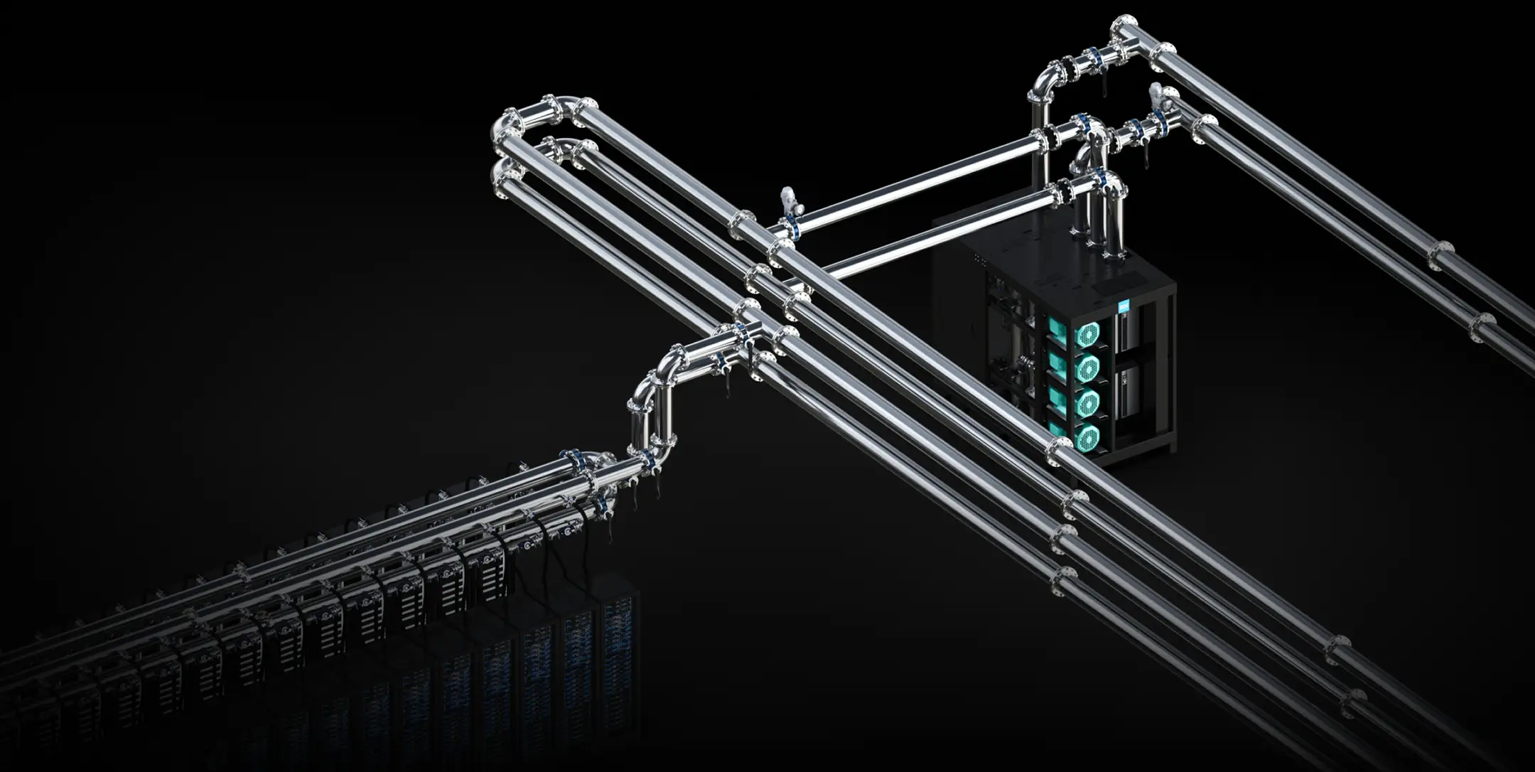
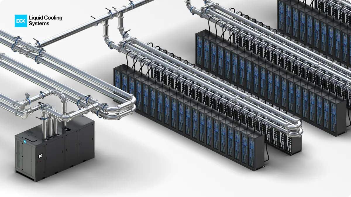
In a liquid cooling system, the Technical Coolant System (TCS) forms the secondary loop between the Coolant Distribution Unit (CDU) and liquid-cooled IT racks. Coolant travels through this shared circuit to remove heat from the IT load. The more racks share the same TCS loop, the more important it becomes to control what enters that loop.
Contamination does not have to originate in the coolant itself. It can be introduced by any component connected to the TCS. Because the TCS is a closed, shared system, a single contaminated component acts as "Patient Zero," spreading debris or chemical impurities across every single connected rack.
A liquid load bank is a good example. Used during thermal commissioning to simulate the load of liquid-cooled racks, it becomes part of the same coolant circuit during testing. If it is not properly flushed, cleaned, and verified before connection, contaminants can be introduced into a loop that has already been prepared and cleaned, potentially forcing the system to undergo another flush-and-fill cycle.
The consequences may develop gradually. Modern high-density cold plates often feature narrow microchannels designed for efficient heat transfer, but these passages can also be vulnerable to particulate accumulation and fouling. As deposits build up, hydraulic resistance may increase, coolant flow may decrease, and heat transfer performance may deteriorate. Changes in differential pressure, flow rates, or cooling performance can provide early indications of developing restrictions.
If these conditions remain undetected or unresolved, insufficient coolant flow or reduced heat transfer can cause component temperatures to rise, potentially triggering thermal throttling, reduced computational performance, or protective shutdowns. In more severe cases, prolonged cooling problems may increase the risk of hardware damage.
A clean loop starts before the coolant goes in
A clean loop does not begin with clean coolant. It begins with the condition of every component that the coolant will eventually touch.
The process starts with the TCS piping. Because the stainless-steel TCS loop is often fabricated in sections offsite, its condition should be verified when it arrives on site. Before these sections are assembled into the loop, they should be checked to ensure they are clean and dry, both inside and out. Welds should also be inspected for discoloration that may indicate improper inert-gas shielding or insufficient passivation, while all wetted materials should be checked against the approved materials list for the selected coolant.
The Coolant Distribution Unit is another critical part of the preparation process. Its secondary circuit should undergo controlled flushing to remove manufacturing residues and particulate contamination before delivery or commissioning. A typical approach involves installing appropriate filters, filling the circuit with an approved flushing fluid, and circulating it under defined conditions. For example, some procedures specify two hours of circulation at the maximum designated flushing flow rate, followed by coolant sampling and filter inspection. Flushing may be repeated until the required cleanliness criteria are achieved.
Verification is equally important. Good practice includes documenting the flushing parameters, fluid type, flow rate, duration, and inspection results. Laboratory analysis of fluid samples and examination of filters can provide measurable evidence that the circuit meets its specified cleanliness requirements.
Once the piping, CDU, and connected components have been properly prepared, flushed, and verified, the system can proceed to its final coolant fill and subsequent commissioning checks. In other words, clean coolant is not what creates a clean loop. It is what enters a loop that should already be clean.
What does “clean” actually mean?
A clean cooling loop is not simply one in which the coolant looks clear. Visual appearance is only one part of the picture. Cleanliness means that particulate contamination is controlled and the coolant's chemical and microbiological properties remain within defined limits compatible with the system's components.
In Technical Cooling Systems (TCS), two distinct processes can compromise coolant quality. The first is chemical degradation, which can occur over time due to thermal exposure, oxidation, and chemical interactions within the cooling system. The second is contamination, which can originate from external sources, such as equipment connected to the loop, or internally through corrosion and degradation of system components.
Verifying coolant cleanliness therefore requires more than visual inspection. It involves testing measurable parameters such as particle concentration and size distribution, pH, conductivity, turbidity, corrosion inhibitor concentration, dissolved metals, and microbial contamination, as applicable to the coolant formulation and system requirements.
Particle contamination is particularly important in direct liquid cooling, where narrow cold plate channels can be vulnerable to fouling and flow restrictions. PG25 has emerged as a key coolant option for next-generation AI hardware, with industry leaders such as NVIDIA reflecting its use in technical specifications.
PG25 is a mixture of 75% water and 25% propylene glycol (PG). At a 25% concentration, PG inhibits bio growth. Interestingly, at 10%, algae and other biomatter tend to feed on PG, but 25% is the sweet spot at which the solution becomes biostatic, meaning it inhibits growth. PG25 also generally includes other additives to further prevent bacterial growth and corrosion in the copper within CDUs and cold plates that carry the fluid.
Each fluid manufacturer uses its own proprietary formulation, but the main goals are to prevent corrosion and bio-growth. The Open Compute Project (OCP) provides specific coolant-quality guidelines for propylene glycol-based fluids used in Technical Cooling Systems (TCS). The following table outlines selected parameters and acceptable ranges for PG25 coolant.
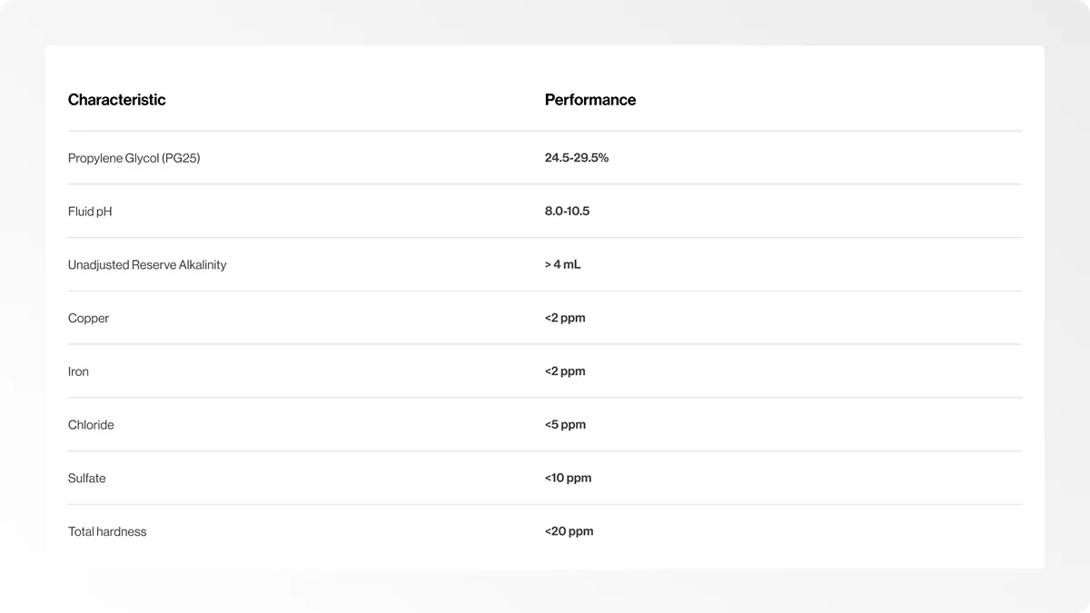
*Values are based on OCP guidelines and may vary depending on the coolant formulation and system-specific requirements.
But measurements alone do not confirm that a coolant is suitable for operation. Compare test results against defined acceptance criteria established by coolant, equipment, and component manufacturers. Establishing baseline measurements during commissioning and repeating tests throughout operation also helps identify gradual changes before they develop into cooling performance issues.
A clean cooling loop is therefore not one that simply appears clean, but one whose coolant quality is measured, documented, and verified against the requirements of the cooling system.
From periodic testing to continuous visibility
Coolant quality does not remain constant once a cooling system is commissioned. Cleanliness must be established before commissioning, verified during system preparation, and maintained throughout operation.
Every new rack connection, maintenance intervention, or interaction with the technical cooling system (TCS) introduces a potential opportunity for contamination. This is why coolant testing must continue throughout the operational life of the cooling infrastructure.
A structured coolant testing program can begin with an initial sample after commissioning, before IT racks are connected to the loop. A second sample may be taken two weeks after rack connection, followed by routine testing every six months. Filter inspections follow a similar six-month schedule, with more frequent checks required when results fall outside the specified limits. Where new racks or other equipment are frequently introduced into the TCS loop, the testing interval can be shortened to quarterly or even monthly, depending on the risk of contamination.
The challenge, however, is not simply determining whether coolant quality meets the required specifications during scheduled testing. It is also understanding how its condition changes between those tests. Laboratory analysis provides detailed information about coolant chemistry, corrosion inhibitor concentration, dissolved metals, and microbial contamination, but periodic sampling alone cannot continuously track the development of these changes.
This is where continuous monitoring provides an additional layer of operational visibility. By tracking pH, conductivity, turbidity, and corrosion-related indicators, operators can identify developing trends and deviations between laboratory tests. Such information can support earlier investigation of potential coolant degradation, contamination, or changes in system condition.
Continuous monitoring does not replace periodic laboratory analysis or physical filter inspections. Instead, it complements these established practices, helping operators maintain greater visibility into coolant quality throughout the cooling system's operational life.
From monitoring to control, inside the DCX 8 MW FDU
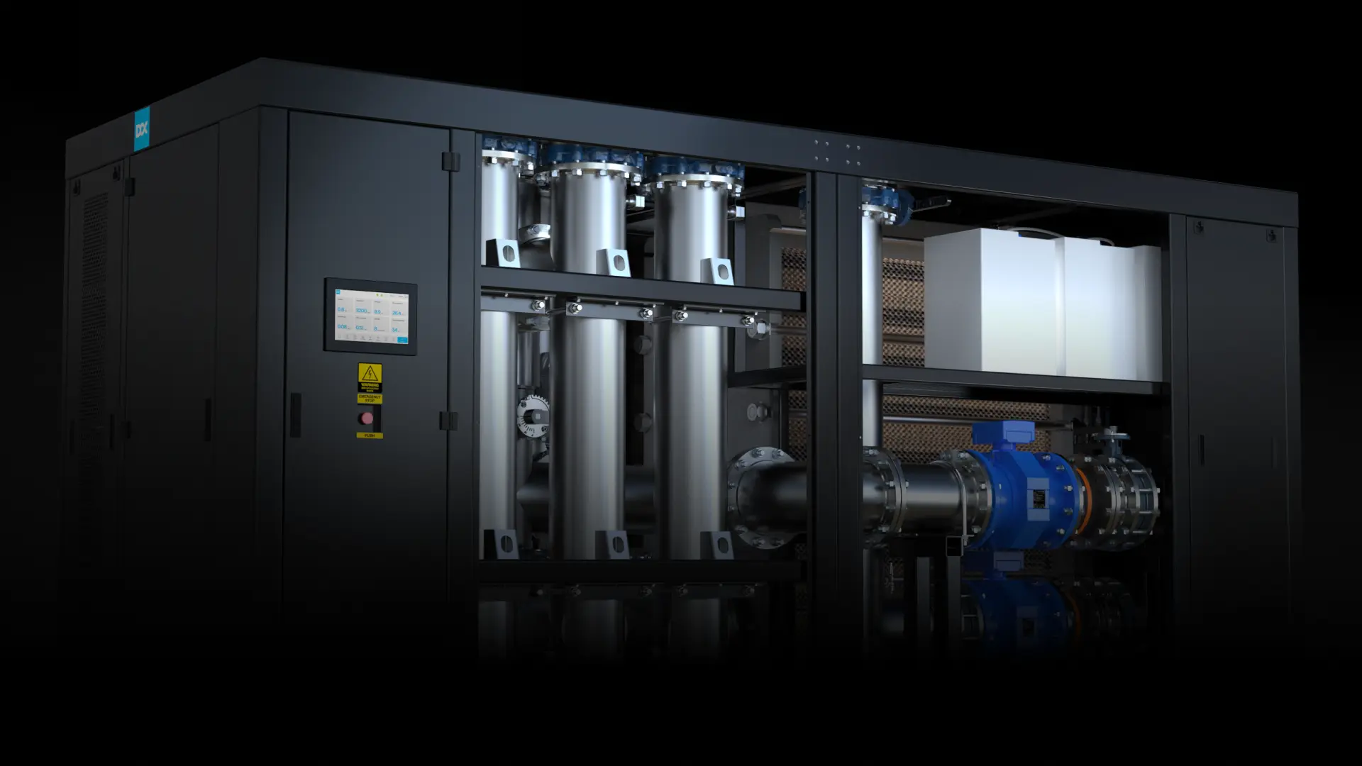
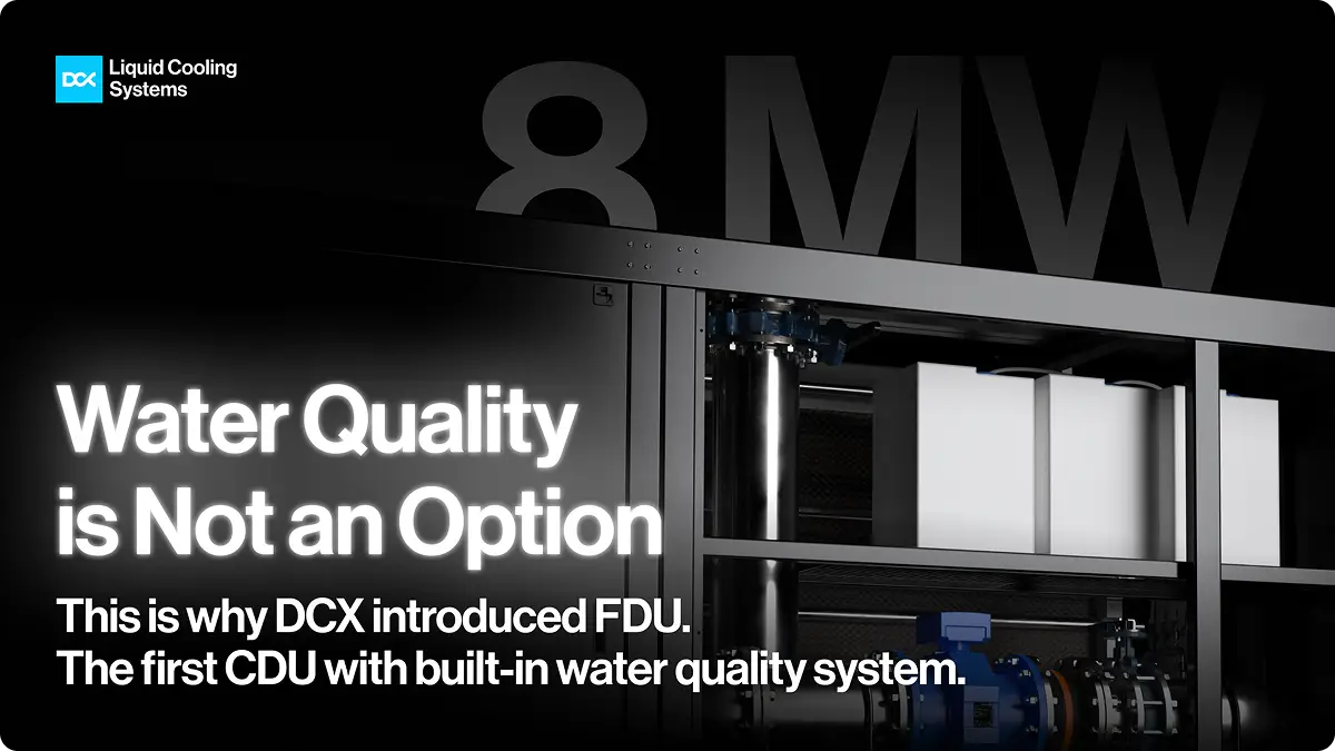
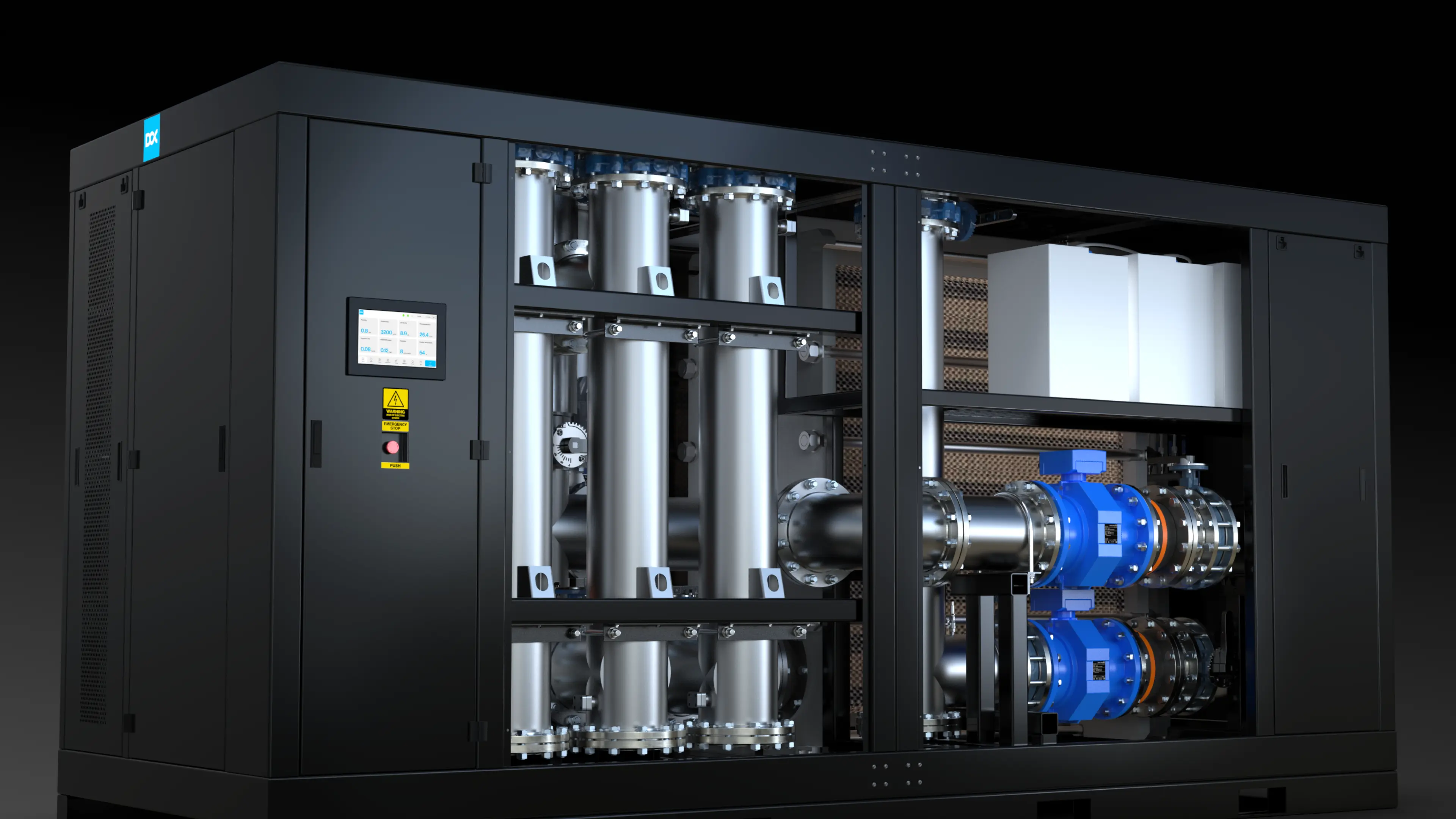
Continuous coolant monitoring is not just a concept. It can be integrated directly into the cooling infrastructure. The DCX 8 MW Facility Distribution Unit (FDU), designed for large-scale AI and hyperscale data centers, combines coolant distribution with built-in water quality monitoring and treatment capabilities.
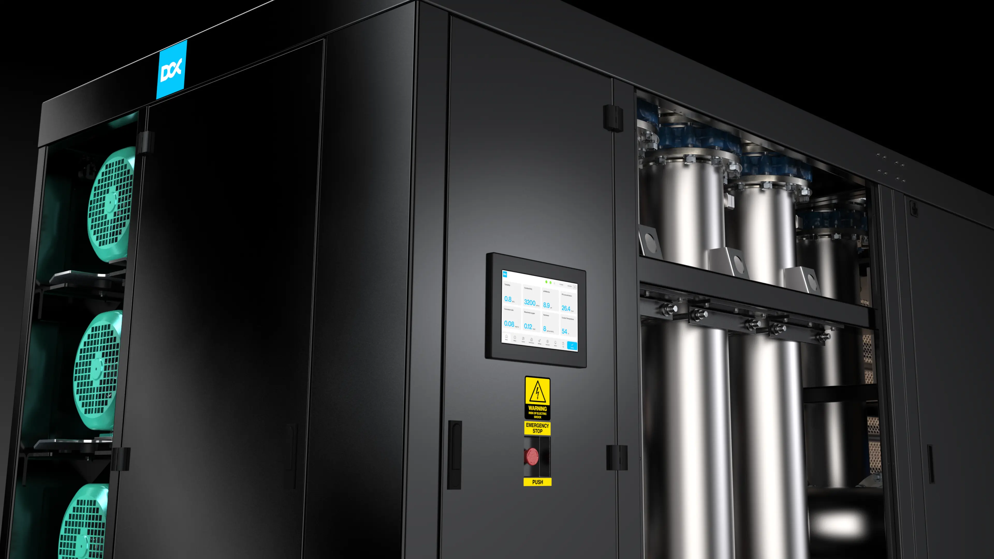
The FDU's touchscreen Human-Machine Interface (HMI) provides operators with direct access to system status, coolant quality, and control functions. The home screen displays an overall “Status OK” indicator alongside a dedicated coolant quality status for PG25 or deionized water, allowing operators to assess the system's condition at a glance.
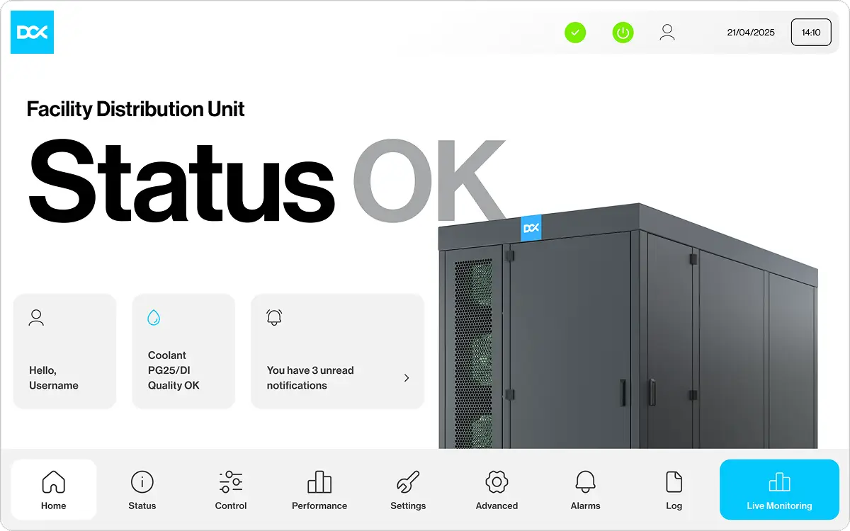
* HMI screens are visual representations of the system. The values and parameters shown are for demonstration purposes only and do not represent actual operating conditions.
For more detail, the live system diagram displays operating parameters across the primary and secondary cooling loops, including temperatures, flow rates, pressures, pump operation, filter differential pressure, and leak detection. This provides a centralized view of the system's hydraulic and thermal performance.
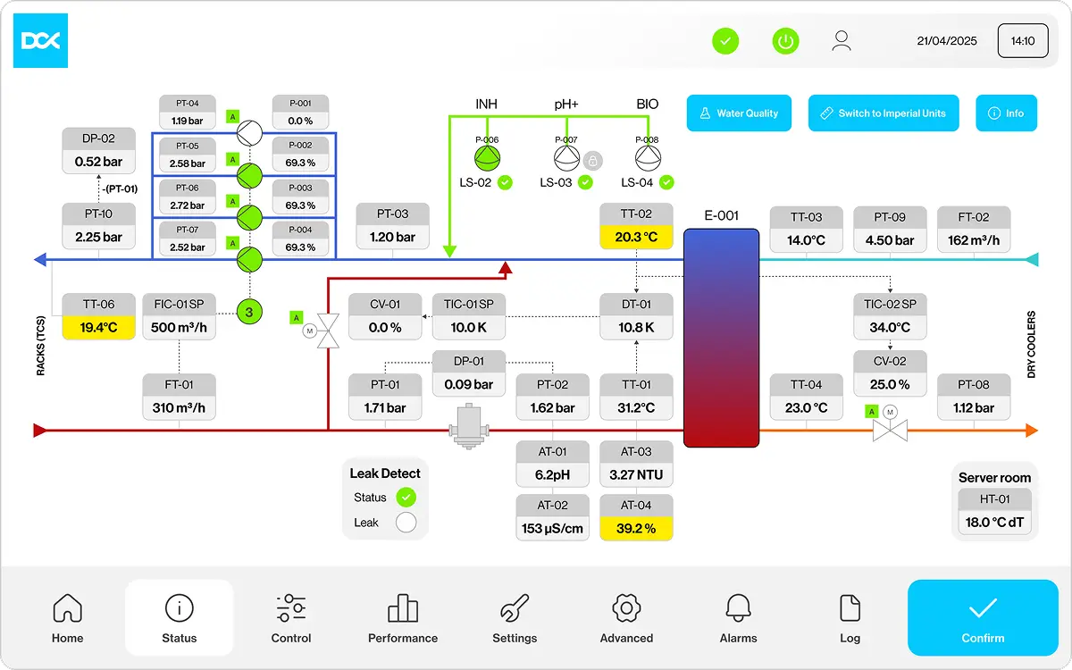
* HMI screens are visual representations of the system. The values and parameters shown are for demonstration purposes only and do not represent actual operating conditions.
A dedicated water-quality dashboard continuously displays eight coolant parameters: turbidity, conductivity, pH, PG concentration, copper corrosion rate, dissolved oxygen, hardness, and coolant temperature. By tracking these measurements over time, operators can identify deviations from defined operating ranges and investigate potential changes in coolant chemistry before they affect cooling performance.
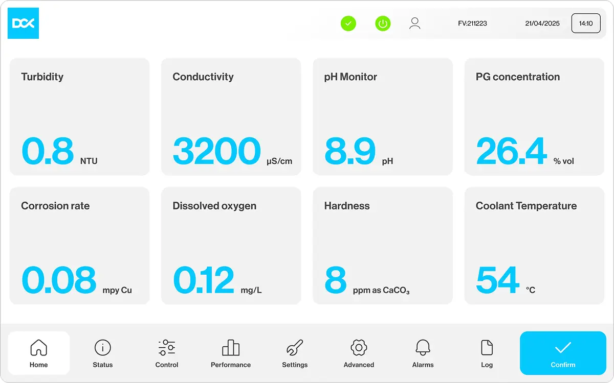
* HMI screens are visual representations of the system. The values and parameters shown are for demonstration purposes only and do not represent actual operating conditions.
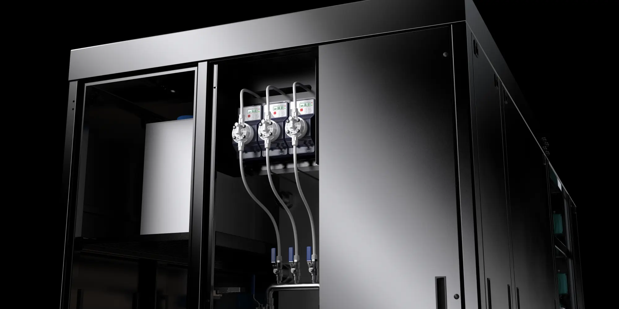
Beyond monitoring, the DCX FDU incorporates an integrated chemical dosing and water treatment system. Three dosing channels support corrosion inhibitor management, pH regulation, and biocide treatment. Configurable dosing parameters, pump operation settings, and treatment controls allow coolant chemistry to be managed according to the system's requirements, reducing the need for manual intervention.
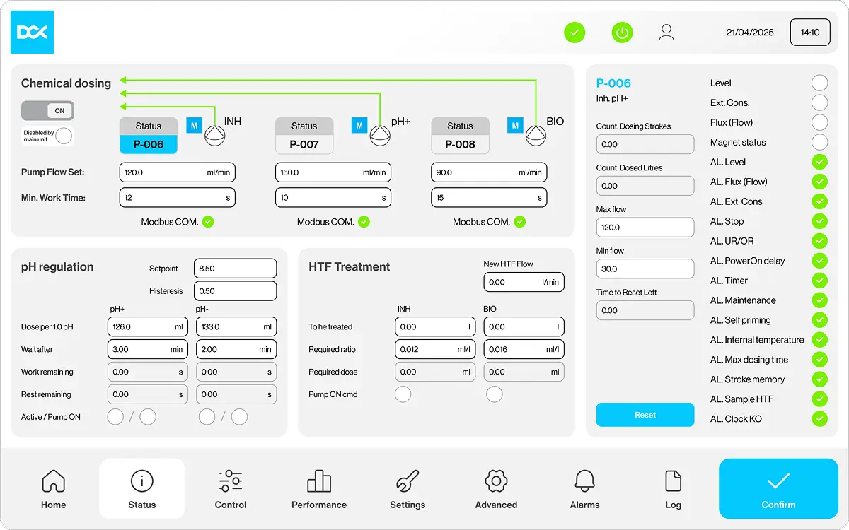
* HMI screens are visual representations of the system. The values and parameters shown are for demonstration purposes only and do not represent actual operating conditions.
The next challenge in liquid cooling is not simply delivering more megawatts, but maintaining reliable cooling performance over years of operation. Cooling capacity, flow rates, and approach temperature are verified at commissioning, but long-term reliability also depends on what happens inside the cooling loop. Coolant cleanliness and chemistry play a critical role in preventing corrosion, fouling, and performance degradation.
This is why the DCX 8 MW FDU goes beyond conventional coolant distribution, integrating continuous water-quality monitoring, automated chemical dosing, and treatment capabilities into a single platform. By making coolant management an integral part of the cooling infrastructure, DCX helps operators maintain coolant quality, protect cooling performance, and reduce operational risks throughout the system's lifecycle.
Sources
1. Liquid Cooling Specifications NVIDIA
2. Guidelines for Using Propylene Glycol-Based Heat Transfer Fluids in Single-Phase Cold Plate-Based Liquid-Cooled Racks
3. What coolant should you use for data center liquid cooling? 22 August 2026
4. Water-Cooled Servers. Common Designs, Components, and Processes ASHRAE
5. How to Assess the Performance of Critical Cooling in Data Centers, 20 March 2026
6. The Unseen Chemistry of AI: The Definitive Guide to Data Center Coolants & Chemicals, 29 August 2025
About DCX Liquid Cooling Systems
DCX Liquid Cooling Systems is a premier global manufacturer offering an extensive range of sustainable liquid cooling solutions, including both Direct Liquid Cooling and Immersion Cooling technologies. The company designs & manufactures Server Immersion Enclosures, Coolant Distribution Units (CDUs) including Hyperscale FDU (Facility sized CDU) system, CPU and GPU coldplates, manifolds and other components of liquid cooling system. DCX delivers Hydro & Immersion Containers and facility-based systems. DCX supplies Immersion Optimised Dry Coolers and a Thermasafe Dielectric Engineered Fluids. Hardware solutions are complemented with liquid cooled data hall design and implementation services, making DCX the first choice for liquid cooling systems’ supplier.
For More Information,
Please Contact
Jacek Dolny
Head of Marketing
jacek.dolny@dcx.eu

We Will Guide You the Whole Time
Everything starts with conversation. Trust us with your project and get us to work on your idea
Invite Us to Your Project
We support both small entities and large enterprises. Initial system design – free of charge.

Let’s Chat with Us
If you have a liquid cooling or heat reuse project – we are yours to talk. Free of charge.

Get the Support
A comprehensive remote, and on-site service. Included with every system we deliver.

Liquid Cooling Explained
Discover the future of data center cooling through a series of short, expert-led videos. Our CTO, Maciek Szadkowski, answers the most important questions, debunks common myths, and reveals what really matters when it comes to modern liquid cooling systems.
Watch the Series
Tell Us About Your Project
The more you tell us up front, the faster we can come back with a real design rather than a brochure. Where possible, include:
- IT load: target capacity in MW, and rack density in kW
- Hardware: GPU or accelerator platform, rack format (19", 21", ORV3), cold plate or immersion
- Loop conditions: available facility water temperature and flow, or "not decided yet"
- Heat rejection: dry coolers, chilled water, district heating, or open
- Site: city and country, plus design ambient temperature
- Timeline: target energisation date and whether this is new build or retrofit
Contact